Pumps- part 2 🚀
- Taliya Mammadhasanzada

- Aug 28, 2020
- 7 min read
Warm greetings to all🌝 in the 25th post on #Day25 ! Today, we will continue learning about the pumps. You can find all written and additional information from this video:
https://youtu.be/pcGTIRGkEyw - Pumps
Here we go 🚀,
Positive-Displacement Pumps 💡
People have designed numerous positive-displacement pumps throughout the centuries. In each design, fluid is sucked into an expanding volume and then pushed along as that volume contracts, but the mechanism that causes this change in volume differs greatly among the various designs. Some designs are very simple, like the flexible-tube peristaltic pump (Fig. 14–26a) that compresses a tube by small wheels, pushing the fluid along. Others are more complex, using rotating cams with synchronized lobes (Fig. 14–26b), interlocking gears (Fig. 14–26c), or screws (Fig. 14–26d). Positive-displacement pumps are ideal for high-pressure applications like pumping viscous liquids or thick slurries, and for applications where precise amounts of liquid are to be dispensed or metered, as in medical applications.

📌To illustrate the operation of a positive-displacement pump, we sketch four phases of half of a cycle of a simple rotary pump with two lobes on each rotor (Fig. 14–27). The two rotors are synchronized by an external gear box so as to rotate at the same angular speed, but in opposite directions. In the diagram, the top rotor turns clockwise and the bottom rotor turns counterclockwise, sucking in fluid from the left and discharging it to the right. A white dot is drawn on one lobe of each rotor to help you visualize the rotation.

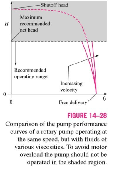
📌📌Gaps exist between the rotors and the housing and between the lobes of the rotors themselves, as illustrated (and exaggerated) in Fig. 14–27. Fluid can leak through these gaps, reducing the pump’s efficiency. High-viscosity fluids cannot penetrate the gaps as easily; hence the net head (and efficiency) of a rotary pump generally increases with fluid viscosity, as shown in Fig. 14–28. This is one reason why rotary pumps (and other types of positive displacement pumps) are a good choice for pumping highly viscous fluids and slurries. They are used, for example, as automobile engine oil pumps and in the foods industry to pump heavy liquids like syrup, tomato paste, and chocolate, and slurries like soups. The pump performance curve (net head versus capacity) of a rotary pump is nearly vertical throughout its recommended operating range, since the capacity is fairly constant regardless of load at a given rotational speed (Fig. 14–28).

🤯However, as indicated by the dashed blue line in Fig. 14–28, at very high values of net head, corresponding to very high pump outlet pressure, leaks become more severe, even for high-viscosity fluids. In addition, the motor driving the pump cannot overcome the large torque caused by this high outlet pressure, and the motor begins to suffer stall or overload, which may burn out the motor. Therefore, rotary pump manufacturers do not recommend operation of the pump above a certain maximum net head, which is typically well below the shutoff head. The pump performance curves supplied by the manufacturer often do not even show the pump’s performance outside of its recommended operating range.
Dynamic Pumps 💡
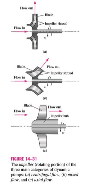
There are three main types of dynamic pumps that involve rotating blades called impeller blades or rotor blades, which impart momentum to the fluid. For this reason they are sometimes called rotodynamic pumps or simply rotary pumps (not to be confused with rotary positive-displacement pumps, which use the same name). There are also some nonrotary dynamic pumps, such as jet pumps and electromagnetic pumps; these are not discussed in this text. Rotary pumps are classified by the manner in which flow exits the pump: centrifugal flow, axial flow, and mixed flow (Fig. 14–31).

💡In a centrifugal-flow pump, fluid enters axially (in the same direction as the axis of the rotating shaft) in the center of the pump, but is discharged radially (or tangentially) along the outer radius of the pump casing. For this reason centrifugal pumps are also called radial-flow pumps. In an axial-flow pump, fluid enters and leaves axially, typically along the outer portion of the pump because of blockage by the shaft, motor, hub, etc. A mixed-flow pump is intermediate between centrifugal and axial, with the flow entering axially, not necessarily in the center, but leaving at some angle between radially and axially.
Centrifugal Pumps 💡
Centrifugal pumps and blowers can be easily identified by their snail-shaped casing, called the scroll (Fig. 14–32).

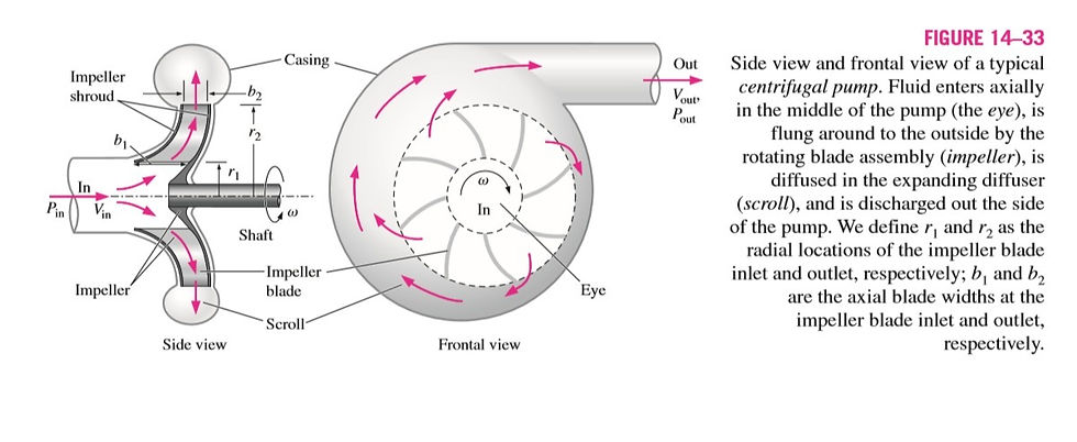
They are found all around your home—in dishwashers, hot tubs, clothes washers and dryers, hairdryers, vacuum cleaners, kitchen exhaust hoods, bathroom exhaust fans, leaf blowers, furnaces, etc. They are used in cars—the water pump in the engine, the air blower in the heater/air conditioner unit, etc. Centrifugal pumps are ubiquitous in industry as well; they are used in building ventilation systems, washing operations, cooling ponds and cooling towers, and in numerous other industrial operations in which fluids are pumped. A schematic diagram of a centrifugal pump is shown in Fig. 14–33.
Learn more: https://youtu.be/pcGTIRGkEyw

🚀Note that a shroud often surrounds the impeller blades to increase blade stiffness. In pump terminology, the rotating assembly that consists of the shaft, the hub, the impeller blades, and the impeller shroud is called the impeller or rotor. Fluid enters axially through the hollow middle portion of the pump (the eye), after which it encounters the rotating blades. It acquires tangential and radial velocity by momentum transfer with the impeller blades, and acquires additional radial velocity by so-called centrifugal forces, which are actually a lack of sufficient centripetal forces to sustain circular motion. The flow leaves the impeller after gaining both speed and pressure as it is flung radially outward into the scroll (also called the volute). As sketched in Fig. 14–33, the scroll is a snail-shaped diffuser whose purpose is to decelerate the fast-moving fluid leaving the trailing edges of the impeller blades, thereby further increasing the fluid’s pressure, and to combine and direct the flow from all the blade passages toward a common outlet.
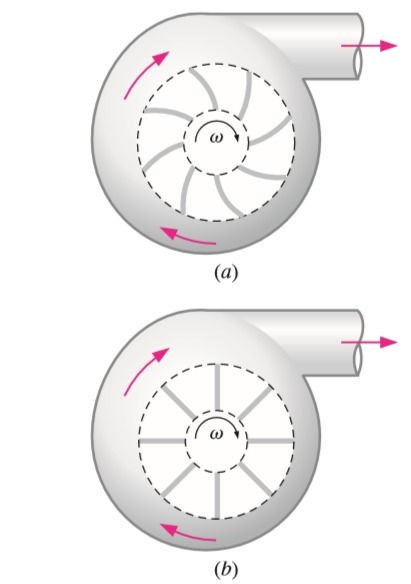
As mentioned previously, if the flow is steady in the mean, if the fluid is incompressible, and if the inlet and outlet diameters are the same, the average flow speed at the outlet is identical to that at the inlet. Thus, it is not necessarily the speed, but the pressure that increases from inlet to outlet through a centrifugal pump. There are three types of centrifugal pump that warrant discussion, based on impeller blade geometry, as sketched in Fig. 14–34: backward-inclined blades, radial blades, and forward-inclined blades.


Centrifugal pumps with backward-inclined blades (Fig. 14-34a) are the most common. These yield the highest efficiency of the three because fluid flows into and out of the blade passages with the least amount of turning. Sometimes the blades are airfoil shaped, yielding similar performance but even higher efficiency. The pressure rise is intermediate between the other two types of centrifugal pumps. Centrifugal pumps with radial blades (also called straight blades, Fig. 14–34b) have the simplest geometry and produce the largest pressure rise of the three for a wide range of volume flow rates, but the pressure rise decreases rapidly after the point of maximum efficiency. Centrifugal pumps with forward-inclined blades (Fig. 14–34c) produce a pressure rise that is nearly constant, albeit lower than that of radial or backward-inclined blades, over a wide range of volume flow rates. Forward-inclined centrifugal pumps generally have more blades, but the blades are smaller, as sketched in Fig. 14–34c. Centrifugal pumps with forward-inclined blades generally have a lower maximum efficiency than do straight-bladed pumps. Radial and backward-inclined centrifugal pumps are preferred for applications where one needs to provide volume flow rate and pressure rise within a narrow range of values.
Additional Notes 🌝
Classification of Impeller
Fully closed- efficient, small amount of suspended bodies (seawater application), good mechanical strength
Semi-closed (semi-open)- average mechanical strength, small amount of suspended bodies
Fully open-inefficient, large amount of suspended bodies (sewage applications), structurally weak
Flow Classification
Radial- most common, applied perpendicular to the shaft. Liquid enters at the center of impeller and is directed out along the impeller blades in a direction at the right angles to pump shaft
Axial- high flow applications. Impeller pushes the liquid parallel to the pump shaft.
Mixed- mixture of axial and radial flow. Impeller blades push the liquid out away from the pump shaft and to the pump suction at angle greater than 90 degree.
Stage classification
Single stage- impeller works in a stage
Multistage- impeller works with 2 and more stages
Pump Impeller
In the impeller design, there is a bore on the middle which is responsible for connecting to the shaft.
🚀The gaps between the vanes in impeller is called channel. In few suspended bodies, there are 5-10 channels (in fresh water), many suspended bodies have less than 5 channels (sewage).
🚀Job of the impeller is convert Kinetic energy to Pressure energy. Prime movers are responsible for the movement of the impeller (electric).
Change in area=Change in Velocity=Change in Pressure
Area increases=Velocity decreases=Pressure increases
Diffuser
The main responsibilities are
converting more Kinetic energy to Pressure energy
increasing efficiency of pump by allowing more gradual expansion
less turbulent are for liquid to reduce velocity
❗️Note: If you want to maximize efficiency of the pump, minimize the liquid leakage from high pressure or discharge side of the pump back to low pressure or suction side.
References📖
Online Technical Session on the topic of "PUMPS" with Tarlan Atayev- https://youtu.be/pcGTIRGkEyw
Fluid Mechanics by Yunus Chengel
Coulson&Richardson-Chemical Engineering Design Vol 6
Introduction to Fluid Mechanics by Edward J.
Additional Resources 🧪🔑
You can get deep insight about Process/Chemical Engineering from these sources😉:
https://www.facebook.com/SPE.BHOS - SPE BHOS arranges technical, soft skill sessions and shares a lot of quizzes, competitions and related books for petroleum and process engineering students
https://www.instagram.com/p/CAXT-ZhlrRW/ Engineerium Mentoring Center Instagram page
https://www.facebook.com/engineeriummentoringcenter Engineerium Mentoring Center Facebook page
http://www2.eng.cam.ac.uk/~mpj1001/learnfluidmechanics.org/LFM_L6.html
https://www.youtube.com/watch?v=NCvYPclQNWM Heat Exchangers Explanation
https://t.me/ebookstorage/210-Introduction to Process Engineering and Design (2015)
https://t.me/ebookstorage/211-Elementary Principles of Chemical Processes
https://t.me/OilAndGas/18122Valve Sizing Sheet
https://t.me/ebookgate/1127Engineering Fluid Mechanics Book
https://coursemania.xyz/course.html?id=433291 Free course on Fundamentals of Fluid Mechanics
https://t.me/ebookstorage/178 Engineering Heat Transfer
https://t.me/ebookstorage/159 Fundamentals of Engineering Thermodynamics (9th Edition) (2018)
https://t.me/ebookstorage/18 Heat Transfer applications and principles
https://t.me/ebookstorage/171-Design and Operation of Heat Exchangers and their Networks (2020)
https://t.me/ebookstorage/215- Industrial Separation Processes (book)
https://t.me/ebookstorage/214- Advanced Process Engineering Control (book)
https://t.me/OilAndGas- Information about Oil&Gas (mainly arabic lang)
https://t.me/chemical_worlds- Chemical Engineering Books, Quizzes and GATE Study Group
https://t.me/chemical_environmental- Discussion group related to Chemical Engineering Problems
https://t.me/chemicalengineeringworld_cew- Everything related to Chemical Engineering
https://t.me/ebookgate- Chemical Engineering E-books (Telegram Channel)
https://www.youtube.com/channel/UCqioh32NOJc8P7cPo3jHrbg- Piping Analysis
https://www.youtube.com/channel/UCQfMyugsjrVUWU0v_ZxQs2Q -Mechanics of engineered devices
http://chemicalengineeringguy.com/- suggests a wide range of courses in Chemical engineering (you can find free courses on topic of Aspen HYSYS, Aspen Plus)
https://www.youtube.com/user/LearnEngineeringTeam- suggests working principles of every engineered devices, equipment and etch.
https://www.youtube.com/channel/UCR0EfsRZIwA5TVDaQbTqwEQ- suggests great information about pumps, compressors with animation.
Today we have learnt about Pumps. Now, time to say goodbye👋🏻 until tomorrow and Stay tuned for more content 😉🌝✨!
✏️Note: If you need one of those books or links, you can contact me via my email or LinkedIn profile.
#process #processengineering #engineering #chemical #chemicalengineering #technical #education #dailypost #newpost #wixsite #day25 #shellandtube #shell #heat #heatexchangers #design #bernoulli #technology #material #materialbalance #mass #massbalance #project #projectengineering #selfdevelopment #challenge #recycle #streams #purge #improvement #fluidflow #flow #centrifugalpumps #fluidmechanics #fluiddynamics #water #waterhammer #reliefvalves #selfactuated #contuinity #energy #equations #Pfd #processdiagrams #diagrams #piping #instrumentation #pid #development #examples #study #studentlife #fluidstatics #valves #gatevalves #globevalves


Comments