Shell and Tube Exchangers: Construction Details (part 1)🧨
- Taliya Mammadhasanzada

- Aug 26, 2020
- 5 min read
Warm greetings to all🤩 in the 22th post on #Day22 ! Today, we will start learning about Shell and Tube Heat Exchangers🤩, here we go✨,
📌The shell and tube exchanger is by far the most commonly used type of heat-transfer equipment used in the chemical and allied industries. The advantages of this type are:
The configuration gives a large surface area in a small volume.
Good mechanical layout: a good shape for pressure operation.
Uses well-established fabrication techniques.
Can be constructed from a wide range of materials.
Easily cleaned.
Well-established design procedures.
📌Essentially, a shell and tube exchanger consists of a bundle of tubes enclosed in a cylindrical shell. The ends of the tubes are fitted into tube sheets, which separate the shell-side and tube-side fluids. Baffles are provided in the shell to direct the fluid flow and support the tubes. The assembly of baffles and tubes is held together by support rods and spacers, Figure 12.2

Exchanger Types
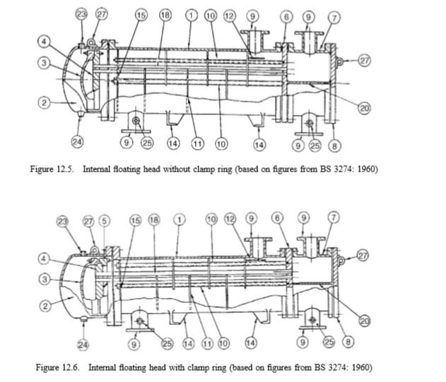
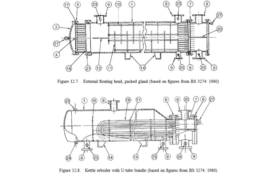
The principal types of shell and tube exchanger are shown in Figures 12.3 to 12.8. Diagrams of other types and full details of their construction can be found in the heat exchanger standards. The standard nomenclature used for shell and tube exchangers is given below;

the numbers refer to the features shown in Figures 12.3 to 12.8.
The simplest and cheapest type of shell and tube exchanger is the
Fixed tube sheet design
shown in Figure 12.3. The main disadvantages of this type are that the tube bundle cannot be removed for cleaning and there is no provision for differential expansion of the shell and tubes. As the shell and tubes will be at different temperatures, and may be of different materials, the differential expansion can be considerable and the use of this type is limited to temperature differences up to about 80C. Some provision for expansion can be made by including an expansion loop in the shell (shown dotted on Figure 12.3)

but their use is limited to low shell pressure; up to about 8 bar. In the other types, only one end of the tubes is fixed and the bundle can expand freely.
The U-tube (U-bundle) type
shown in Figure 12.4 requires only one tube sheet and is cheaper than the floating-head types; but is limited in use to relatively clean fluids as the tubes and bundle are difficult to clean. It is also more difficult to replace a tube in this type.
Exchangers with an internal floating head, Figures 12.5 and 12.6, are more versatile than fixed head and U-tube exchangers. They are suitable for high-temperature differentials and, as the tubes can be rodded from end to end and the bundle removed, are easier to clean and can be used for fouling liquids. A disadvantage of the pull-through design, Figure 12.5, is that the clearance between the outermost tubes in the bundle and the shell must be made greater than in the fixed and U-tube designs to accommodate the floating head flange, allowing fluid to bypass the tubes.
The clamp ring (split flange design),
Figure 12.6, is used to reduce the clearance needed. There will always be a danger of leakage occurring from the internal flanges in these floating head designs.
🧨In the external floating head designs, Figure 12.7, the floating-head joint is located outside the shell, and the shell sealed with a sliding gland joint employing a stuffing box. Because of the danger of leaks through the gland, the shell-side pressure in this type is usually limited to about 20 bar, and flammable or toxic materials should not be used on the shell side.


Baffles 🧨
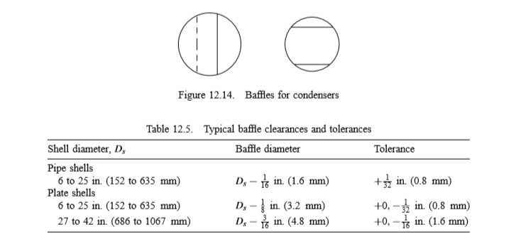
Baffles are used in the shell to direct the fluid stream across the tubes, to increase the fluid velocity and so improve the rate of transfer. The most commonly used type of baffle is the single segmental baffle shown in Figure 12.13a, other types are shown in Figures 12.13b, c and d. If the arrangement shown in Figure 12.13a were used with a horizontal condenser the baffles would restrict the condensate flow. This problem can be overcome either by rotating the baffle arrangement through 90, or by trimming the base of the baffle, Figure 12.14.
🤔The term “baffle cut” is used to specify the dimensions of a segmental baffle. The baffle cut is the height of the segment removed to form the baffle, expressed as a percentage of the baffle disc diameter. Baffle cuts from 15 to 45 per cent are used. Generally, a baffle cut of 20 to 25 per cent will be the optimum, giving good heat-transfer rates, without excessive drop. There will be some leakage of fluid round the baffle as a clearance must be allowed for assembly. The clearance needed will depend on the shell diameter; typical values, and tolerances, are given in Table 12.5


😱Another leakage path occurs through the clearance between the tube holes in the baffle and the tubes. The maximum design clearance will normally be 1-32 in. (0.8 mm). The minimum thickness to be used for baffles and support plates are given in the standards. The baffle spacing used range from 0.2 to 1.0 shell diameters.
📌A close baffle spacing will give higher heat transfer coefficients but at the expense of higher pressure drop. The optimum spacing will usually be between 0.3 to 0.5 times the shell diameter.
References📖
Coulson&Richardson-Chemical Engineering Design Vol 6
https://www.sacome.com/en/heat-exchanger-advantages-uses-applications/
https://www.explainthatstuff.com/how-heat-exchangers-work.html
http://www.thermex.co.uk/news/blog/160-what-is-a-heat-exchanger
Additional Resources 🧪🔑
You can get deep insight about Process/Chemical Engineering from these sources😉:
http://www2.eng.cam.ac.uk/~mpj1001/learnfluidmechanics.org/LFM_L6.html
https://www.youtube.com/watch?v=NCvYPclQNWM Heat Exchangers Explanation
https://t.me/ebookstorage/210-Introduction to Process Engineering and Design (2015)
https://t.me/ebookstorage/211-Elementary Principles of Chemical Processes
https://t.me/OilAndGas/18122Valve Sizing Sheet
https://t.me/ebookgate/1127Engineering Fluid Mechanics Book
https://coursemania.xyz/course.html?id=433291 Free course on Fundamentals of Fluid Mechanics
https://t.me/ebookstorage/178 Engineering Heat Transfer
https://t.me/ebookstorage/159 Fundamentals of Engineering Thermodynamics (9th Edition) (2018)
https://t.me/ebookstorage/18 Heat Transfer applications and principles
https://t.me/ebookstorage/171-Design and Operation of Heat Exchangers and their Networks (2020)
https://t.me/ebookstorage/215- Industrial Separation Processes (book)
https://t.me/ebookstorage/214- Advanced Process Engineering Control (book)
https://t.me/OilAndGas- Information about Oil&Gas (mainly arabic lang)
https://t.me/chemical_worlds- Chemical Engineering Books, Quizzes and GATE Study Group
https://t.me/chemical_environmental- Discussion group related to Chemical Engineering Problems
https://t.me/chemicalengineeringworld_cew- Everything related to Chemical Engineering
https://t.me/ebookgate- Chemical Engineering E-books (Telegram Channel)
https://www.youtube.com/channel/UCqioh32NOJc8P7cPo3jHrbg- Piping Analysis
https://www.youtube.com/channel/UCQfMyugsjrVUWU0v_ZxQs2Q -Mechanics of engineered devices
http://chemicalengineeringguy.com/- suggests a wide range of courses in Chemical engineering (you can find free courses on topic of Aspen HYSYS, Aspen Plus)
https://www.youtube.com/user/LearnEngineeringTeam- suggests working principles of every engineered devices, equipment and etch.
https://www.youtube.com/channel/UCR0EfsRZIwA5TVDaQbTqwEQ- suggests great information about pumps, compressors with animation.
Today we have continued learning about Heat Exchangers. Now, time to say goodbye👋🏻 until tomorrow and Stay tuned for more content 😉🌝✨!
✏️Note: If you need one of those books or links, you can contact me via my email or LinkedIn profile.
#process #processengineering #engineering #chemical #chemicalengineering #technical #education #dailypost #newpost #wixsite #day22 #shellandtube #shell #heat #heatexchangers #design #bernoulli #technology #material #materialbalance #mass #massbalance #project #projectengineering #selfdevelopment #challenge #recycle #streams #purge #improvement #fluidflow #flow #fluidmechanics #fluiddynamics #water #waterhammer #reliefvalves #selfactuated #contuinity #energy #equations #Pfd #processdiagrams #diagrams #piping #instrumentation #pid #development #examples #study #studentlife #fluidstatics #valves #gatevalves #globevalves


Comments